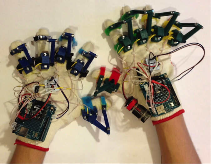
入门篇:Arduino蓝牙手套第一部分-基础
本项目的目的是开发一种能够检测出操作员的手和手指方位的设备,以实现机器人的控制。我们将介绍有关电阻和分压器的基础知识。另外,我们还将了解如何通过 I2C 总线从陀螺仪和加速度计获取测量值,以及如何建立 Arduino–PC蓝牙连接。该设备在集成到 Arduino蓝牙手套中之后将会发挥出它的作用。
硬件
- • Arduino UNO
- • 面包板
- • 电位计 0-10kOhm
- • 电阻 10 kOhm
- • IMU 传感器
- • 电线
- • Arduino 无线扩展板
- • Xbee USB 适配器
- • Bluetooth Bee
- • PC 蓝牙适配器
- • USB A-B 数据线
- • 微型 USB 数据线
软件
- • Arduino IDE 1.6.7
- • LabVIEW
工具
- • 万用表
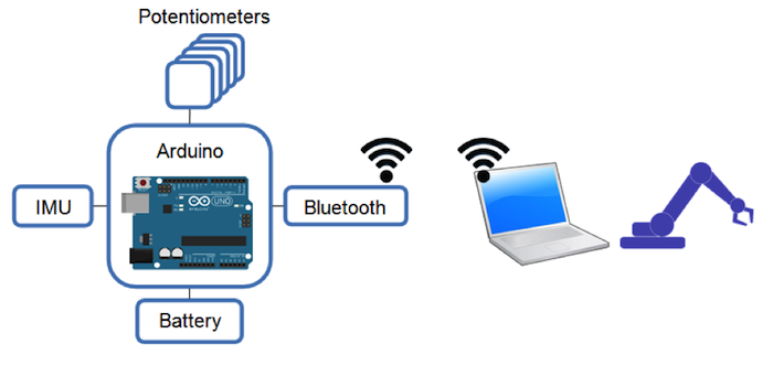
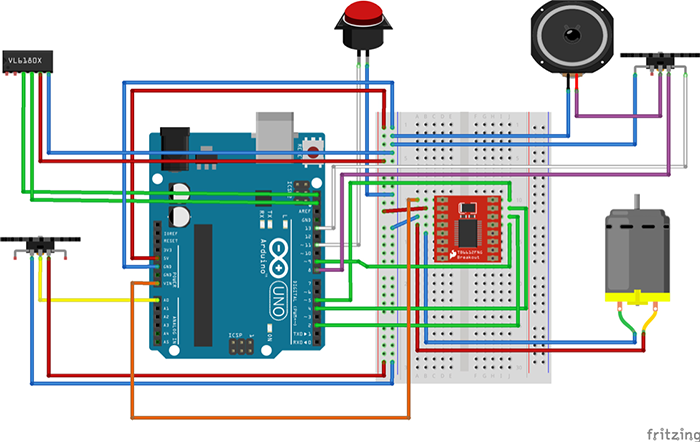
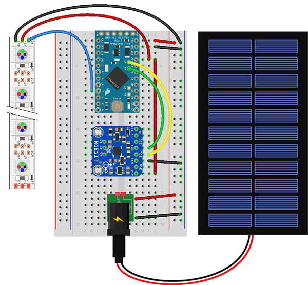
图1: Arduino蓝牙手套项目的基本示意图
基于Arduino的采集系统配置在用户的每只手上。Arduino开发板通过测量每个电位计的电阻来获取手指弯曲(手指弯折)的信息。在处理了来自惯性测量单元(IMU)的数据后,可以识别出用户手的方位,该单元包括陀螺仪和加速度计。电池和无线数据传输模式使基于 Arduino的采集系统可用作一个可穿戴智能手套。例如,它可以用作手动控制机器人手臂的通用输入设备。
旋转测量
当旋转从手指传递到电位器手柄时,可以通过测量每个电位计的电阻来识别手指的弯曲。可使用分压器来测量电位计电阻。如果想要降低电压并获得某些固定值,可以在电路中使用分压器,由两个或多个电阻组成。
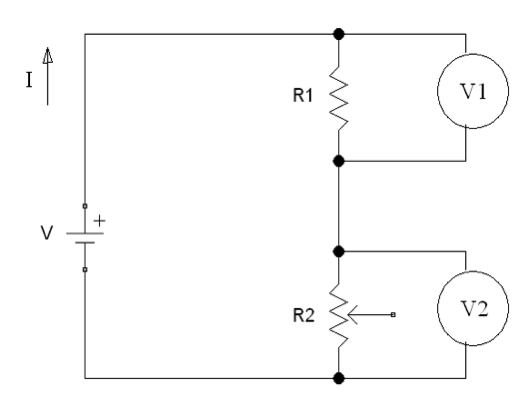
图2:分压器电路图
V 是来自Arduino 5V电源的电压; I 是 流经电路的电流; R1是具有固定电阻值的电阻; R2 是具有可变电阻的电位计; V1和V2是电压表。
电压在电阻R1和R2处均产生压降。V1和V2之和为V的值。根据欧姆定律:
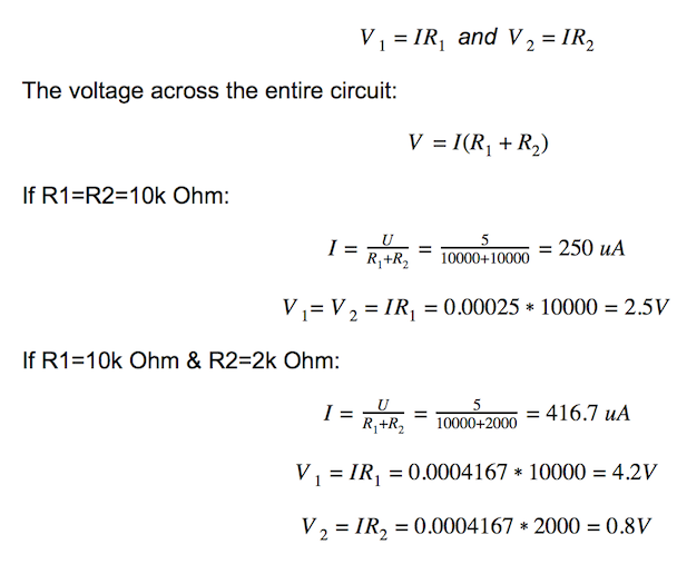
用Arduino模拟输入代替V2电压表,以测量电位计的电阻。
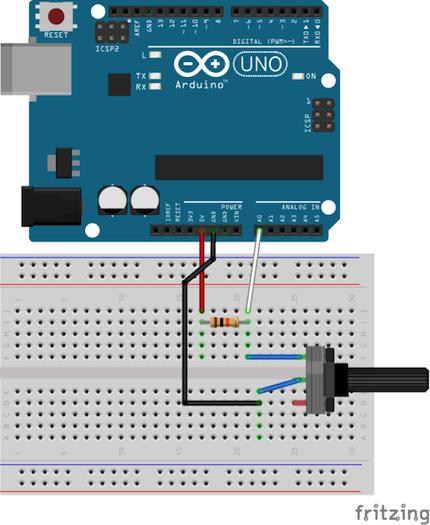
图3:分压器电路示意图
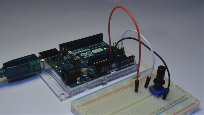
图4:安装在面包板上的分压器电路
int sensorValue;
void setup()
{
  Serial.begin(9600);// initialize serial communication at 9600 bits per second
}

void loop()
{
  sensorValue = analogRead(A0);// read the input on analog pin 0
  Serial.println(sensorValue);// print out the value you read
  delay(100);        // delay in between reads for stability
}
定向测量
惯性测量单元(IMU)是一种可以测量人体比力和角速度的电子设备。通过对角速度的连续积分,我们可以获得安装有IMU传感器的物体的当前方向。
得益于MEMS技术,IMU传感器开始流行并被广泛使用。大多数MEMS IMU传感器利用 I2C协议作为将测量结果发送到控制器的主要方式。
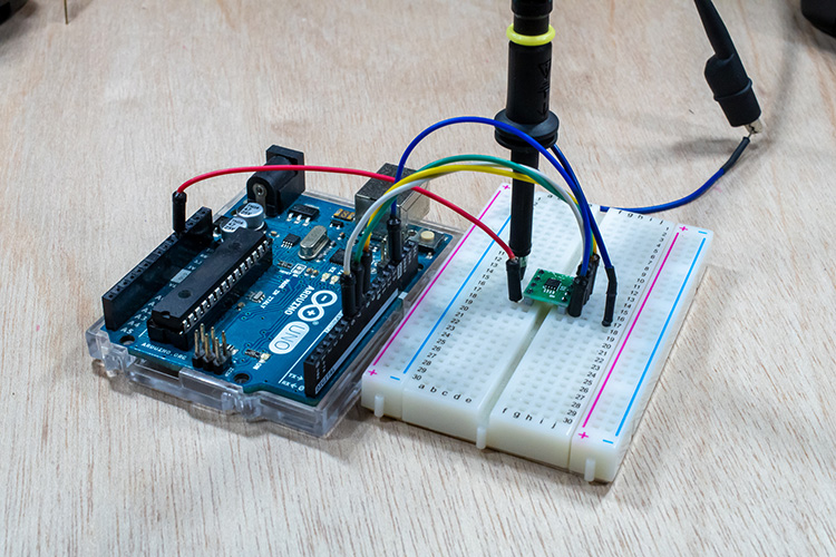
您必须为芯片提供电源(V和G),并将数据和时钟引脚(D和C)连接到相应的数字引脚(SDA和SCL),如图5所示:
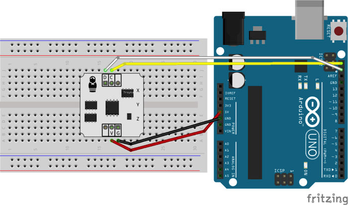
图5:IMU传感器连接
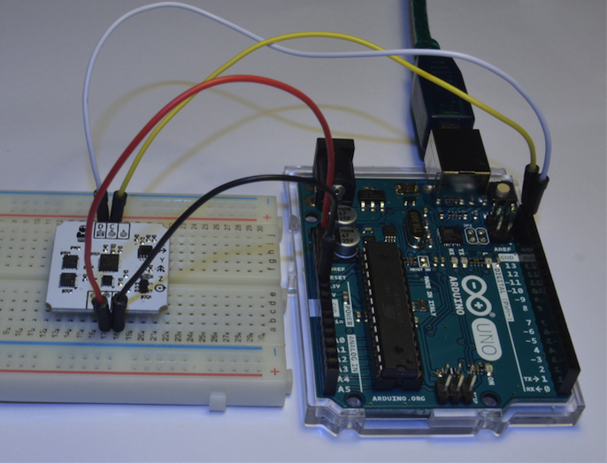
图6:连接到Arduino开发板的IMU传感器
通常,来自不同制造商的IMU传感器都会具有相同的结构,即所有的MEMS芯片都连接到 I2C 总线。因此,要从陀螺仪、加速度计和磁力计获取测量值,您将仅使用这两个引脚。
我们这里使用的IMU传感器包含 STMicroelectronics芯片( L3G4200D和 LIS331DLH )。如果您使用包含不同MEMS芯片的IMU传感器,可以更改源代码中的地址使其工作。
现在,让我们进行测试程序吧!
您需要下载安装 IMU 库 (点击Github上的“View Raw”来下载 IMU_Sensor.zip )。
将.ZIP Library 添加到 Arduino IDE( Sketch >> Include Library >> Add .ZIP Library…)
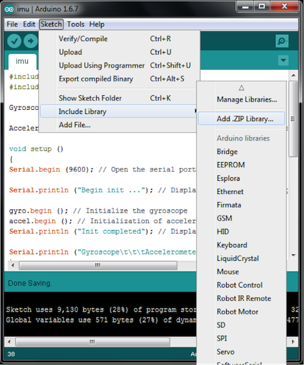
图7: Arduino IDE上添加.ZIP Library
您将会在 Arduino libraries文件夹中看到 IMU_Sensor库(图8)。现在,我们将使用“#include ”测试IMU传感器。
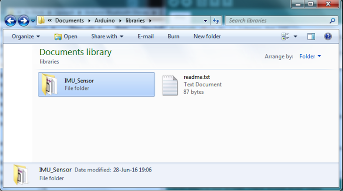
图8:Arduino libraries文件夹中出现的 IMU_Sensor库
#include <Wire.h> // Library for I²C
#include <imu.h> // Library for working with IMU modules

Gyroscope gyro; // Create an object to work with Gyroscope

Accelerometer accel; // Create an object to work with Accelerometer

void setup ()
{
Serial.begin (9600); // Open the serial port

Serial.println ("Begin init ..."); // Display a message on the beginning of the initialization

gyro.begin (); // Initialize the gyroscope
accel.begin (); // Initialization of accelerometers
Serial.println ("Init completed"); // Display a message about the successful initialization

Serial.println ("Gyroscope\t\t\tAccelerometer");
}

void loop ()
{
Serial.print (gyro.readX_DegPerSec ()); // Output angular velocity around the axis X
Serial.print ("\t");
Serial.print (gyro.readY_DegPerSec ()); // Output of the angular velocity around the Y axis
Serial.print ("\t");
Serial.print (gyro.readZ_DegPerSec ()); // Output of the angular velocity about the Z axis
Serial.print ("\t\t");

Serial.print (accel.readX_G ()); // Output of the direction and magnitude of acceleration along the X axis
Serial.print ("\t");
Serial.print (accel.readY_G ()); // Output of the direction and magnitude of acceleration along the Y-axis
Serial.print ("\t");
Serial.print (accel.readZ_G ()); // Output of the direction and magnitude of acceleration along the Z axis
Serial.print ("\t\t");

Serial.println ("");
delay (300);
}
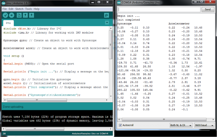
图9:IMU传感器输出
无线数据传输
可以使用 Bluetooth Bee(无线蓝牙BT模块)来建立无线连接。 Bluetooth Bee模块带有板载天线。它的作用就像一个透明串行端口,可与各种蓝牙适配器和蓝牙手机配合使用。
为了检查蓝牙模块配置,请将开关置于AT模式。当模块处于AT模式时,用户或主机微控制器可以通过经串行端口发送预定义的AT指令来对其进行配置。在AT模式下,您可以从BT模块获取服务数据并更改某些设置(名称,波特率,奇偶校验和停止位)。
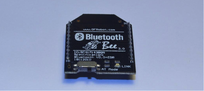
图10:开关置于AT模式的 Bluetooth Bee
将BT模块和 Xbee适配器堆叠在一起,然后通过微型USB电缆将 Xbee适配器连接到PC。LED灯必须处于打开状态。
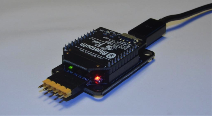
图11: Bluetooth Bee 放置于 Xbee适配器上
启动Arduino IDE,从 Tools >> Serial Port菜单中选择与 Xbee适配器对应的COM端口。
打开 Arduino的串行监视器( Tools >> Serial Monitor或者Ctrl+Shift+M )。如果COM端口没有正常显示,请安装 Xbee USB适配器驱动程序。从相应的选项栏中选择“Both NL & CR”、“38400”来更改PC的串行设置,以读取来自 Xbee适配器的信息,或写入需要输入到 Xbee 适配器中的信息。
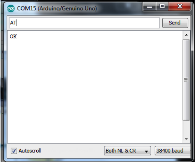
发送“AT”并接收到“OK”。
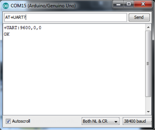
发送“AT+UART?”并接收串行设置,如“9600,0,0”。
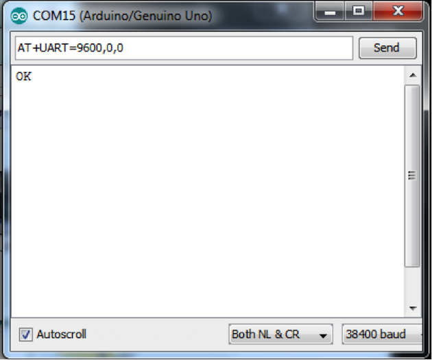
如果您接收到的串行设置不是“9600,0,0”,那么发送“AT+UART=9600,0,0”指令并接收到“OK”。
关闭串行监视器,断开 Xbee适配器与微型 USB数据线和BT模块的连接。不要忘记向左旋转开关来关闭AT模式。
将 Bluetooth Bee放置在 Arduino无线扩展板上,将 Arduino与USB A-B数据线连接,如图12所示。
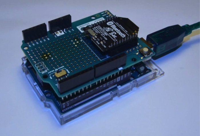
图12:在 Arduino无线扩展板上的 Bluetooth Bee
完成此步骤后,您将可以使用默认的“我的蓝牙设备”窗口找到您的 Bluetooth Bee。将您的 Bluetooth Bee与默认密码“1234”配对。请注意连接到您的设备的是哪个COM端口,在下一步草图中选择该COM端口。
这是用于测试蓝牙连接的 Arduino草图。(请注意,当将 Bluetooth Bee 安装到 Arduino无线扩展板上时,您将无法启用草图)。
#define LED 13
int pause = 0;    // variable to store sent value

void setup()
{
  pinMode(LED, OUTPUT);
  Serial.begin(9600);  // open the serial port
}

void loop()
{
  if (Serial.available() > 0) {
    // read incoming serial data:
    String inStr = Serial.readString();
    Serial.println("Get Message:"+inStr);
    pause = inStr.toInt();
    }

  digitalWrite(LED, HIGH);   // turn the LED on (HIGH is the voltage level)
  delay(pause);              // wait for a second
  digitalWrite(LED, LOW);    // turn the LED off by making the voltage LOW
  delay(pause);              // wait for a second
}
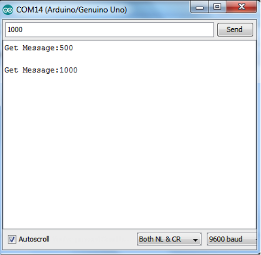
图13:测试 Bluetooth Bee连接
如果您有任何意见或疑问,请在 Google + 上给我们留言。请在该主页继续关注我们,我们将会尽快发布更多资讯。
Ivan Petrov
一名嵌入式系统开发以及自动化领域的工程师。Ivan热衷于通过以移动机器人技术、AI技术和控制理论为基础构建项目来不断挑战自己。