这篇文章来源于DevicePlus.com英语网站的翻译稿。

本文最初发布在deviceplus.jp网站上,而后被翻译成英语。
目录
前言
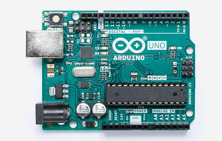
本文中,我将介绍一种不一样的Arduino使用方式。乍一看,照片中的Arduino看起来像我们之前系列中使用过的Arduino Pro Mini,但其实这是另一种Arduino。它被称为“Arduino Pro Micro”。虽然“Mini”变成了“Micro”,尺寸却并没有发生任何变化,因此,两者有点难以区分。这种Arduino在连接到电脑时会被识别为鼠标或键盘等HID设备。
电子设计步骤
预计完成时间:60分钟
所需元器件
- Arduino主机(Arduino Pro Micro)
- 面包板
- 双轴操纵杆模块#27800
- 轻触开关
- 220Ω 电阻
- LED
1. 关于Arduino Pro Micro
Arduino Pro Micro是一种Arduino,配备有名为“ATmega32U4”的芯片(UNO等配有ATmega328P等)。该芯片最大的特点是当通过USB连接时会伪装成键盘和鼠标等人机接口设备(HID)。配备ATmega32U4的Arduino除了“Pro Micro”之外,还被称为“Arduino Leonardo”,是非常有名的开发板。
在编写程序时,您可以选择名为“Arduino Leonardo.”的开发板。

乍一看,Arduino Pro Mini与Arduino Pro Micro的外观非常相似。
但是,Pro Micro具有可以连接到智能手机等设备的USB连接器,而Pro Mini只有一个串行连接器。
2. 使之被识别为HID
现在,我们让外观相似的Arduino Pro Micro读取示例程序并尝试让电脑将其识别为HID。
尝试运行Arduino IDE的“File”-“Sketch Example”-“09.USB”-“Keyboard”-“KeyboardMessage”程序。
在这个程序中,我们创建一个在引脚4上设有开关的简单电路,当引脚4被按下时,应通过键盘输入显示按下的次数。
(这次,我将引脚4改换为引脚7)

#include "Keyboard.h"

const int buttonPin = 7; // input pin for pushbutton
int previousButtonState = HIGH; // for checking the state of a pushButton
int counter = 0; // button push counter

void setup() {
 // make the pushButton pin an input:
 pinMode(buttonPin, INPUT);
 // initialize control over the keyboard:
 Keyboard.begin();
}

void loop() {
 // read the pushbutton:
 int buttonState = digitalRead(buttonPin);
 // if the button state has changed,
 if ((buttonState != previousButtonState)
 // and it's currently pressed:
 && (buttonState == HIGH)) {
 // increment the button counter
 counter++;
 // type out a message
 Keyboard.print("You pressed the button ");
 Keyboard.print(counter);
 Keyboard.println(" times.");
 }
 // save the current button state for comparison next time:
 previousButtonState = buttonState;
}

编写程序并打开记事本后,无需触碰键盘,每按一次按钮,就会按照上面的描述进行计数。
如果可以如此轻松地制作USB设备,那么就可以实现更多梦想!
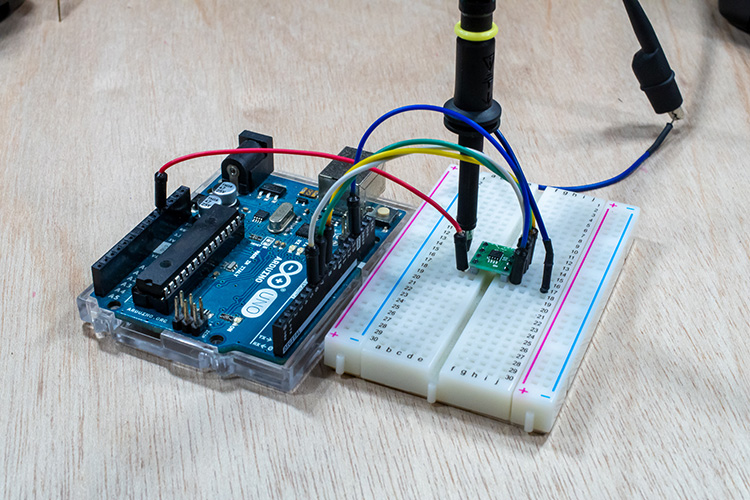
3. 使用操纵杆创建鼠标设备
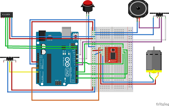
我们已经知道Arduino Pro Micro可以用作HID,下面我想通过将它与其他一些元器件组合来创建鼠标设备。这一次,我将使用曾经在无线电控制设备制作中使用过的操纵杆,并尝试创建一个可以用操纵杆和轻触开关来代替鼠标的设备。
首先,准备一个可用于设置操纵杆方向的程序。


将电路添加到之前的轻触开关电路中。将操纵杆和后面要使用的LED连接到引脚2。
Code Example
const int _UDPIN = A0; // UD Input
const int _LRPIN = A1; // LR Input
const int _SWPIN = 7; // Digital Pin
int _UD = 0; // Value for Up/Down
int _LR = 0; // Value for Left/Right

void setup() {
 Serial.begin(9600);
 pinMode(_SWPIN,INPUT) ;
}

void loop() {
 _UD = analogRead(_UDPIN);
 _LR = analogRead(_LRPIN);
 Serial.print("UP-DOWN:");
 Serial.print(_UD, DEC);
 Serial.print(" - Left-Rright:");
 Serial.println(_LR, DEC);
 if (digitalRead(_SWPIN) == HIGH) {
 Serial.println("switch on");
 }
 delay(100);
}

经过确认,可以知道它读取了程序,转动操纵杆时数字会发生变化。
接下来,让我们将操纵杆数字值转换为鼠标坐标。实际上,这个程序也是已经备好的示例程序,所以让我们来用用看。请选择“File”-“Sketch Example”-“09.USB”-“Mouse”-“JoystickMouseControl”。
执行此程序时,会将上下(模拟引脚A2)和左右(模拟引脚A1)的值反映在鼠标坐标上。此外,由于引脚2通过接入5V电源来实现开关功能的,因此可以通过将引脚2与VCC相连或将开关夹在中间的方式来打开/关闭设备。
Code Example
#include "Mouse.h"

// set pin numbers for switch, joystick axes, and LED:
const int switchPin = 5; // switch to turn on and off mouse control
const int mouseButton = 7; // input pin for the mouse pushButton
const int xAxis = A1; // joystick X axis
const int yAxis = A2; // joystick Y axis
const int ledPin = 2; // Mouse control LED

// parameters for reading the joystick:
int range = 12; // output range of X or Y movement
int responseDelay = 5; // response delay of the mouse, in ms
int threshold = range / 4; // resting threshold
int center = range / 2; // resting position value

boolean mouseIsActive = false; // whether or not to control the mouse
int lastSwitchState = LOW; // previous switch state

void setup() {
pinMode(switchPin, INPUT); // the switch pin
pinMode(ledPin, OUTPUT); // the LED pin
// take control of the mouse:
Mouse.begin();
}

void loop() {
// read the switch:
int switchState = digitalRead(switchPin);
// if it's changed and it's high, toggle the mouse state:
if (switchState != lastSwitchState) {
if (switchState == HIGH) {
mouseIsActive = !mouseIsActive;
// turn on LED to indicate mouse state:
digitalWrite(ledPin, mouseIsActive);
}
}
// save switch state for next comparison:
lastSwitchState = switchState;

// read and scale the two axes:
int xReading = readAxis(A0);
int yReading = readAxis(A1);

// if the mouse control state is active, move the mouse:
if (mouseIsActive) {
Mouse.move(xReading, yReading, 0);
}

// read the mouse button and click or not click:
// if the mouse button is pressed:
if (digitalRead(mouseButton) == HIGH) {
// if the mouse is not pressed, press it:
if (!Mouse.isPressed(MOUSE_LEFT)) {
Mouse.press(MOUSE_LEFT);
}
}
// else the mouse button is not pressed:
else {
// if the mouse is pressed, release it:
if (Mouse.isPressed(MOUSE_LEFT)) {
Mouse.release(MOUSE_LEFT);
}
}

delay(responseDelay);
}

/*
reads an axis (0 or 1 for x or y) and scales the
analog input range to a range from 0 to
*/

int readAxis(int thisAxis) {
// read the analog input:
int reading = analogRead(thisAxis);

// map the reading from the analog input range to the output range:
reading = map(reading, 0, 1023, 0, range);

// if the output reading is outside from the
// rest position threshold, use it:
int distance = reading - center;

if (abs(distance) < threshold) {
distance = 0;
}

// return the distance for this axis:
return distance;
}
完成编程后,我们来尝试让它动起来。
哦,它真的动起来了!
结论
这次,我们学习了使用Arduino Pro Micro创建基于Arduino的USB设备时的基本流程。在下一篇文章中,我们将进一步深化应用Arduino Pro Micro,尝试创建更具“Device Plus”风格的USB设备,让项目更具挑战性!
相关文章
还能用Arduino完成哪些项目?可以浏览相关文章更多了解:
- 可以用Arduino来制作USB设备吗? 利用Arduino Pro Micro (Leonardo)来创建设备
- 如何将您的Arduino连接到Wi-Fi
- 如何通过Windows电脑控制Arduino
- 如何使用手势控制您的电脑
- 如何使用遥控器向您的项目发送IR指令
DevicePlus 编辑团队
设备升级版适用于所有热爱电子和机电一体化的人。